Eterna Global Solutions
C-52 Block-C, Sector 80
Noida Uttar Pradesh,
201306, India
Eterna Global Solutions
C-52 Block-C, Sector 80
Noida Uttar Pradesh,
201306, India
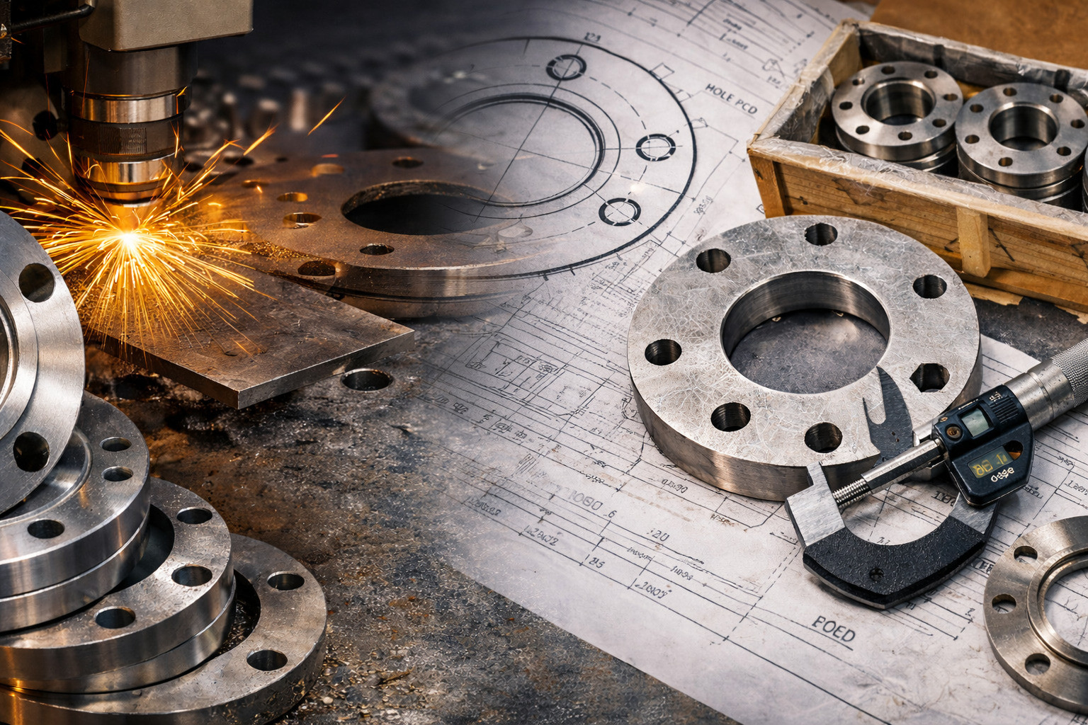
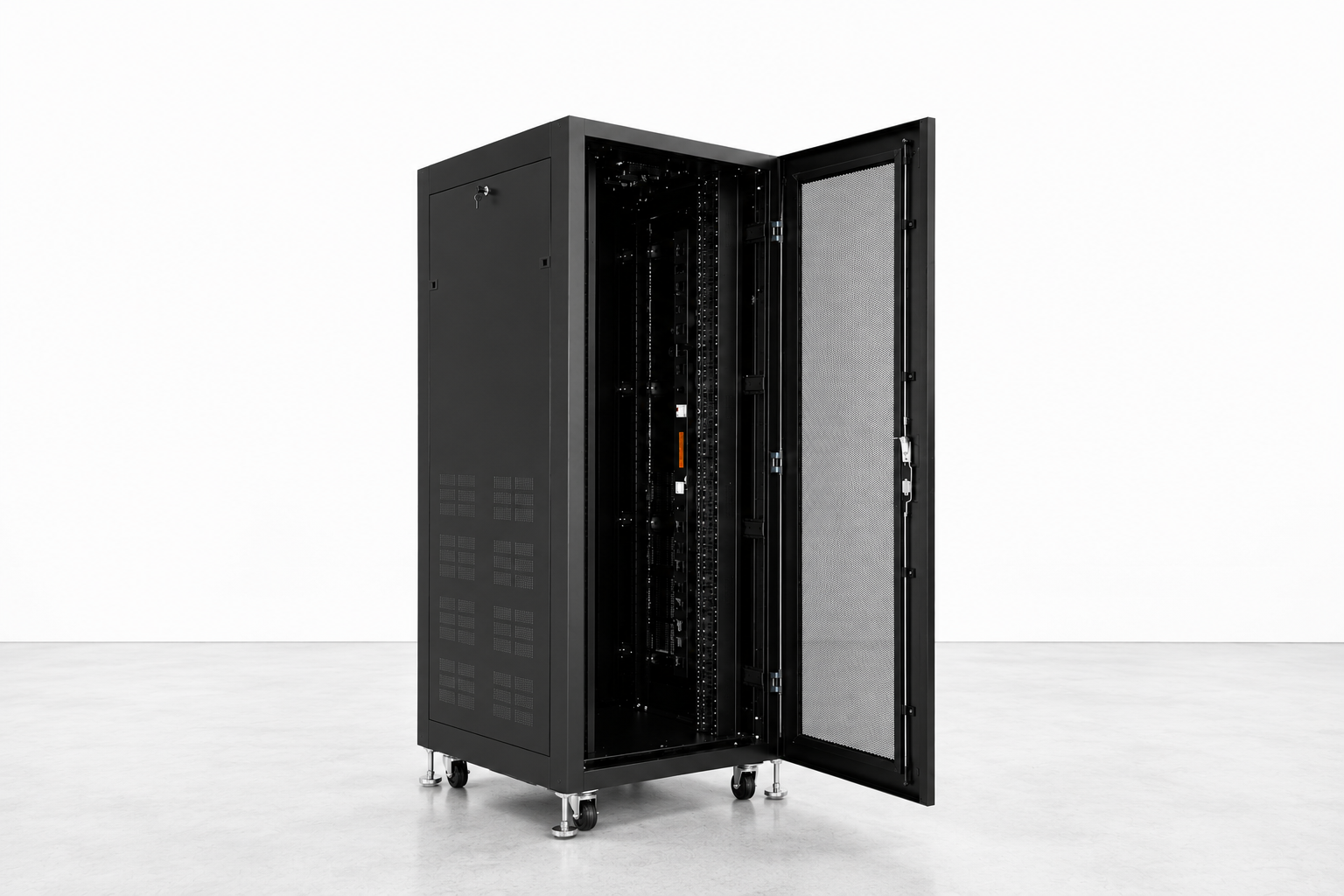
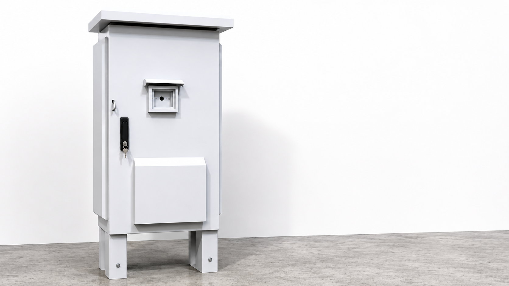
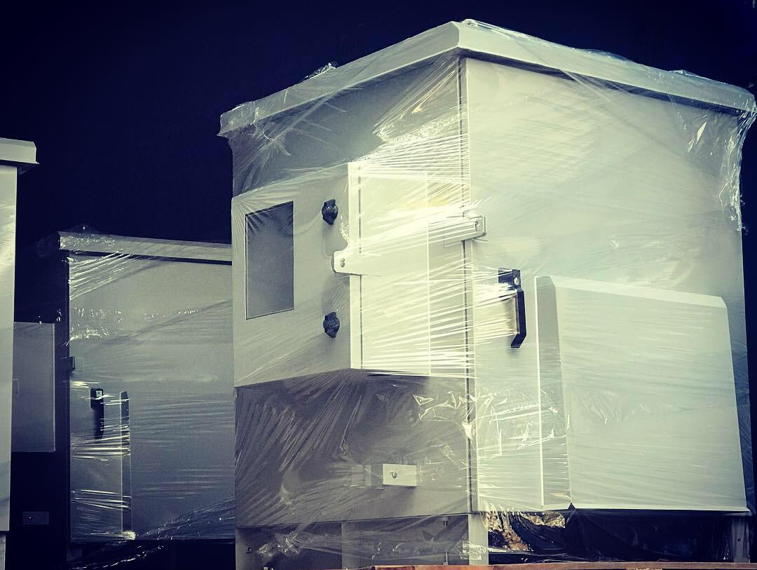
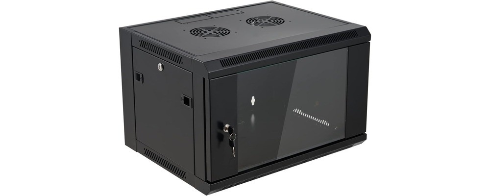
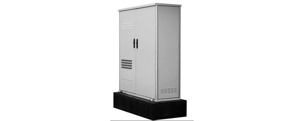
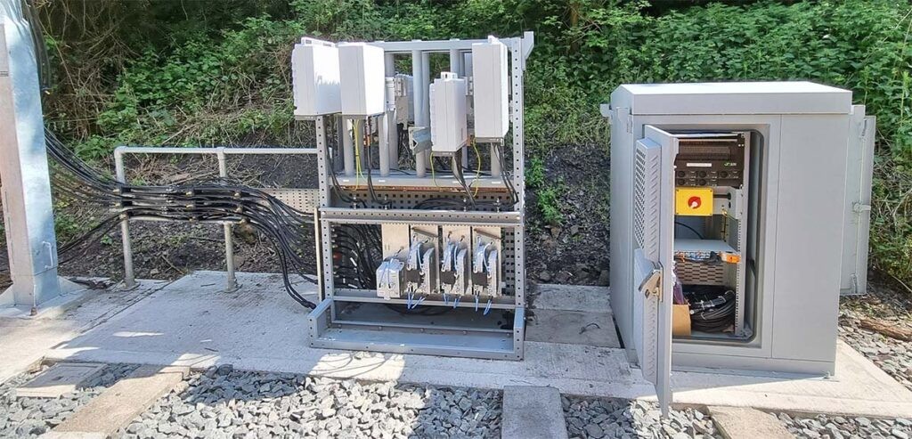
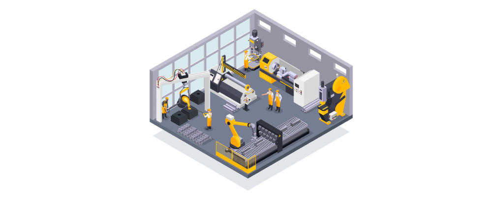
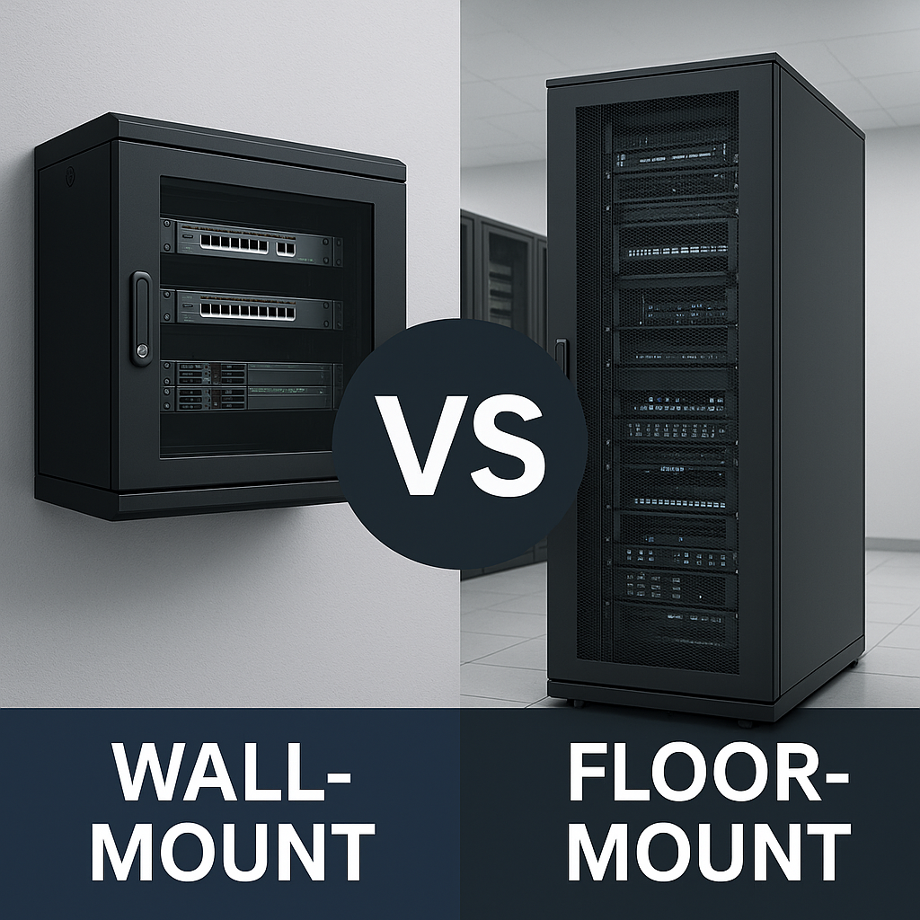
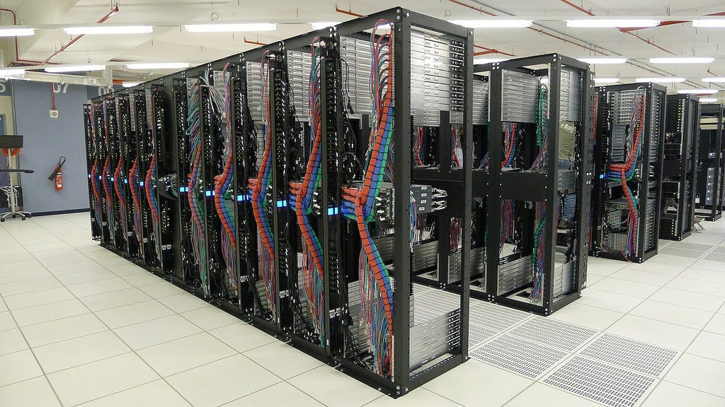
Eterna Global Solutions LLP provides Design for Manufacturing (DFM) engineering for OEMs developing sheet metal enclosures, server racks, telecom cabinets, EV/BESS enclosures, and fabricated assemblies. DFM is the engineering discipline of reviewing a design before manufacturing begins and modifying it to be easier, faster, more reliable, and more cost-effective to produce — without compromising functional performance. The same enclosure can meet the same specification yet cost 15–30% more simply because of avoidable design choices: an over-toleranced dimension, a bend too close to a hole, a weld joint with poor access, or a flat pattern that wastes sheet stock.
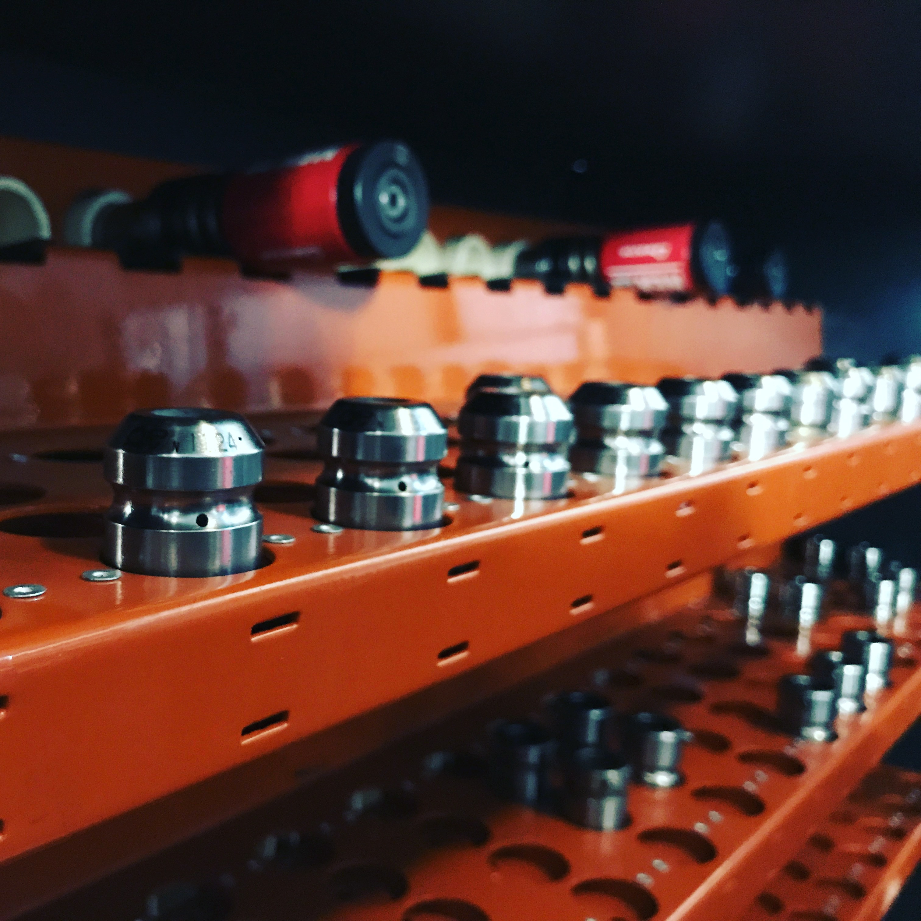
Most manufacturing problems are not discovered in CAD — they appear on the shop floor: hole distortion after bending, warpage after welding, inconsistent fit at assembly, coating defects caused by poor masking access, and rework driven by unrealistic tolerances. Eterna’s DFM process is manufacturer-led: our engineers review your design with the realities of our fiber lasers, press brakes, welding fixtures, and powder coating line in mind. This ensures recommendations are practical and aligned to real production capability, not generic textbook rules.
Whether you are launching a new product, localising an imported enclosure, redesigning for cost reduction, or qualifying a second source, a structured DFM review prevents scrap, rework, and schedule delays from compounding across every future production batch.
Without DFM, manufacturability issues surface late: bend radii that crack on stainless steel, hole patterns that distort because they sit too close to bend lines, weld seams that require complex fixtures, doors that don’t seal because of tolerance stack-up, and coating failures caused by poor masking access. These failures drive scrap, rework, and repeated iterations — and every issue costs more as the product moves from drawing to cutting, forming, welding, coating, and assembly.
We review your design against our process capability and real production failure modes. You receive a written report categorising issues as Critical (must-fix) and Recommended (cost/quality improvements), with clear corrective actions. The outcome is a production-ready design that runs smoothly through cutting, forming, welding, coating, and assembly — and stays repeatable batch after batch.
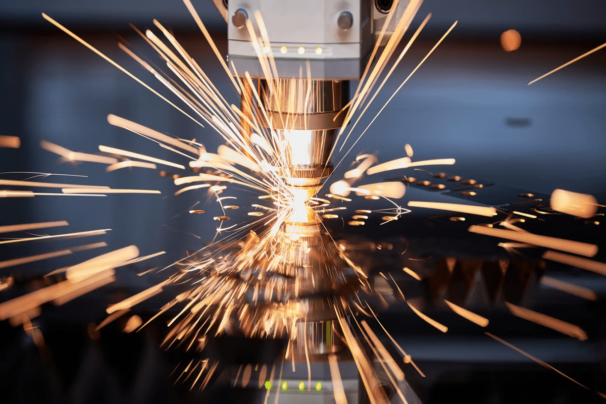
We evaluate whether the flat pattern nests efficiently on standard sheet sizes and whether feature geometry is laser-friendly and stable.
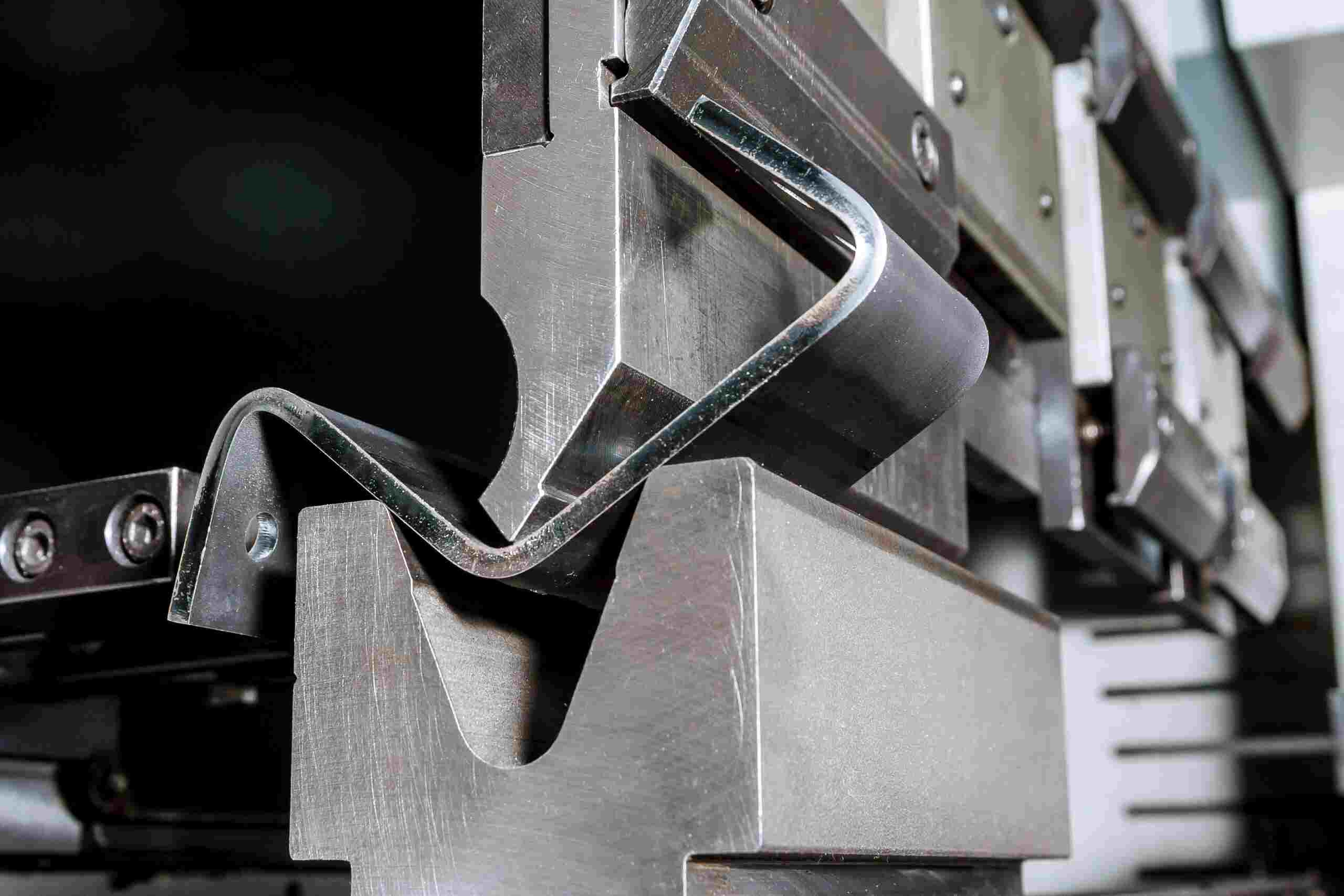
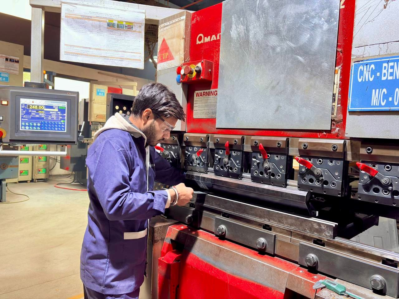
We validate bend feasibility, sequence collisions, and distortion risks using real shop-floor constraints.
We assess weld joint geometry and accessibility, and recommend changes that reduce fixture complexity and warpage.
We validate assembly practicality and finishing requirements so production does not slow down at the last mile.
Don’t over-tolerance: Tight tolerances increase scrap and inspection cost. We recommend tolerances that match functional need.
Hole-to-bend distance: Keep holes and slots away from bend tangents to prevent distortion; add reliefs if proximity is unavoidable.
Minimum flange length: Short flanges can be unstable in the press brake and create inconsistent angles; we flag risky features early.
Reliefs at bend intersections: Proper corner relief prevents tearing on multi-bend corners.
Design for access: If a weld cannot be accessed cleanly, it becomes slow, inconsistent, and cosmetic issues increase.
Reduce heat input: Long continuous welds warp thin sheet; stitch patterns and joint redesign reduce distortion and rework.
Standardise fasteners: Fewer fastener types speeds assembly and reduces error rates.
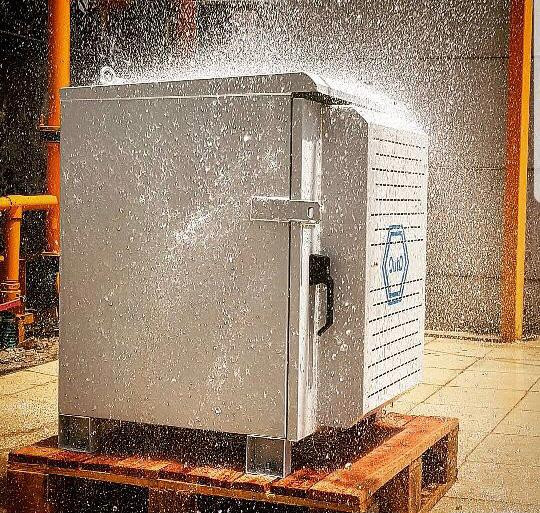
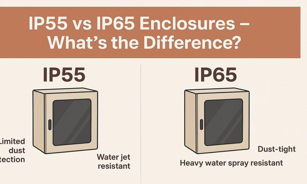
Plan masking: Provide clearance for masking at threads and gasket lands to prevent coating failures.
Design intake
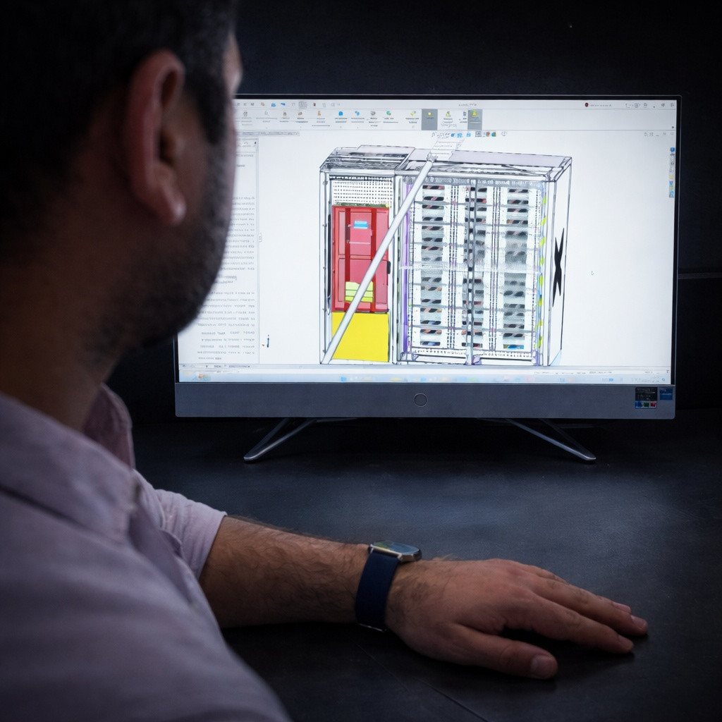
CAD + drawings + BOM + functional context
We review your file pack and clarify functional requirements that affect manufacturability.
Manufacturability review
Cutting • forming • welding • coating • assembly
We identify risks and improvements across the entire process chain.
DFM report delivered
Findings • solutions • impact summary
You receive a written DFM report with clear corrective actions.
Review call & design lock
Approve changes • revise drawings • proceed to NPI
We walk through recommendations and lock a DFM-approved revision for prototyping or first production.
DFM identifies dimension tweaks that improve sheet utilisation, consolidates parts to reduce welding, and simplifies forming to cut cycle time. It also reduces risk features that drive scrap and rework.
DFM reduces assembly fit issues, improves repeatability, and prevents late-stage failures (like coating defects and door sealing issues) that create schedule delays. The result is fewer iterations and faster time-to-production.
Share your CAD + drawing pack — we return a written DFM report within 3–5 working days.


-20082508144130.jpg)
-20082508385589.jpg)


-29112509574730.jpg)
-18122502213226.png)