-07112406183830.jpg)

Eterna Global Solutions
C-52 Block-C, Sector 80
Noida Uttar Pradesh,
201306, India
Eterna Global Solutions
C-52 Block-C, Sector 80
Noida Uttar Pradesh,
201306, India
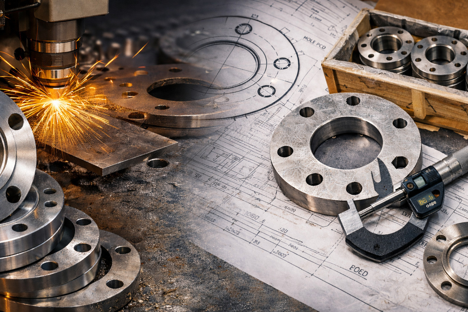
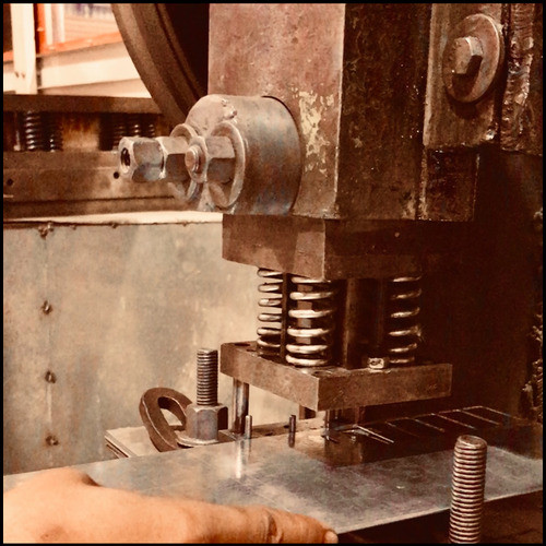
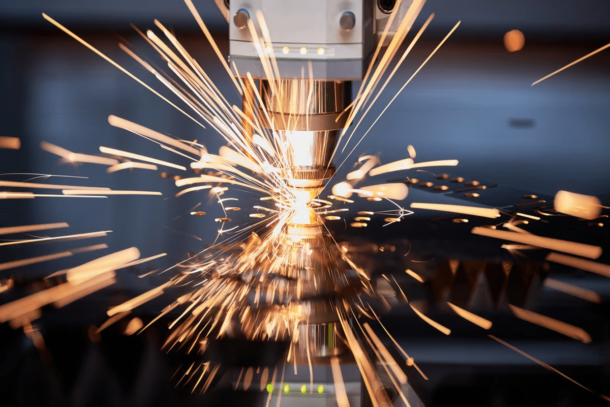
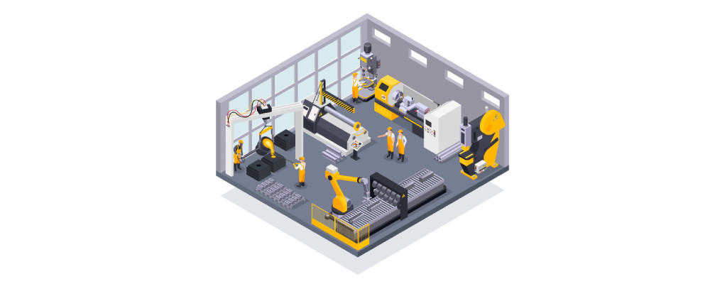
Eterna Global Solutions LLP operates in-house stamping presses and shearing machines at its Noida manufacturing facility for high-volume production of fixed-geometry sheet metal components. When a part design is finalised and volumes justify dedicated tooling, stamping delivers the lowest per-piece cost, the fastest cycle times, and the highest part-to-part consistency of any sheet metal production method. Our stamping capability complements our CNC laser blanking operation — laser cutting handles prototypes, short runs, and complex contours, while stamping takes over for high-volume repeat production where speed and material efficiency are the priority.
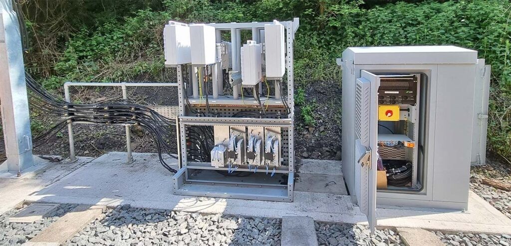
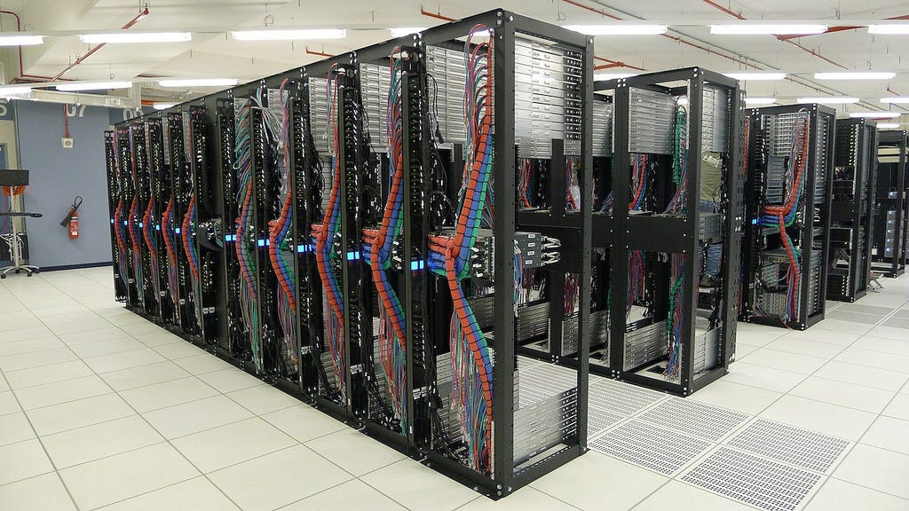
Our press shop produces brackets, mounting plates, cable clamps, earth bars, gussets, reinforcement ribs, hinge plates, lock strikers, ventilation louvres, blanked panels, and other fixed-geometry components used inside server racks, telecom cabinets, battery enclosures, and OEM assemblies. Each part is produced using a dedicated press tool (die set) that performs blanking, piercing, forming, or a combination of operations in a single stroke or progressive sequence. This means every part in a batch of 1,000 or 10,000 is dimensionally identical — no variation from part to part, no operator-dependent quality differences.
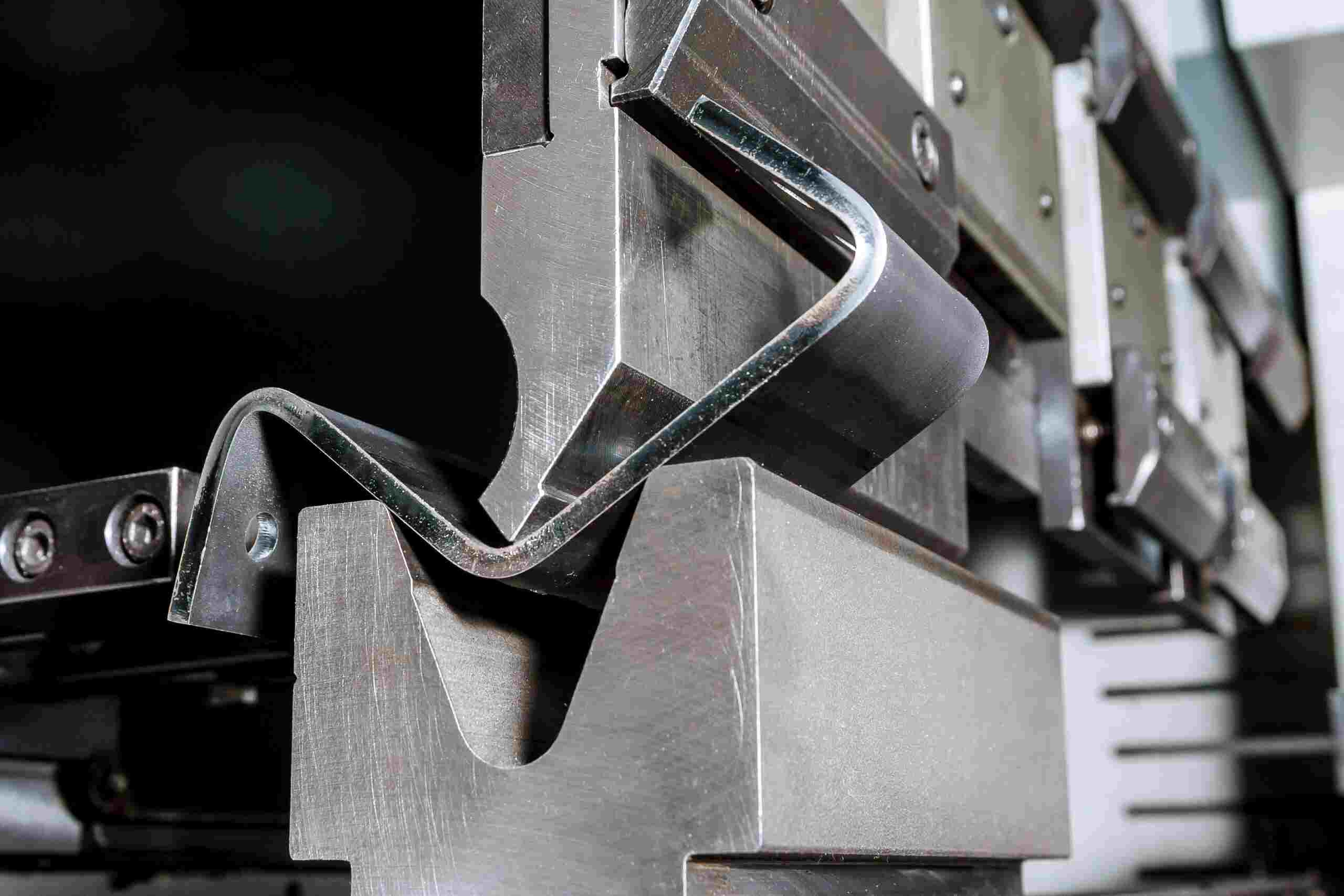
Stamping is a cold-forming process where a press forces a sheet metal workpiece into or through a die set to produce a part with a specific shape, hole pattern, or form in a single stroke. The die set — consisting of a punch (upper tool) and die (lower tool) — is custom-built for each part geometry and mounted in a mechanical or hydraulic press. Because the tool defines the part shape, every piece produced is dimensionally identical, making stamping ideal for high-volume production of fixed-geometry components where consistency, speed, and low per-piece cost are critical.
Shearing is a straight-line cutting process where a blade descends across a sheet of metal to separate it into smaller blanks. Unlike laser cutting, shearing produces zero kerf loss — no material is vaporised or consumed during the cut — making it the most material-efficient method for producing rectangular and square blanks. Our shears cut full-size sheets (typically 2,500 × 1,250 mm or 2,000 × 1,000 mm) down to the blank size required for stamping or direct use, with optimised cutting sequences that maximise the number of blanks per sheet and minimise offcut waste.
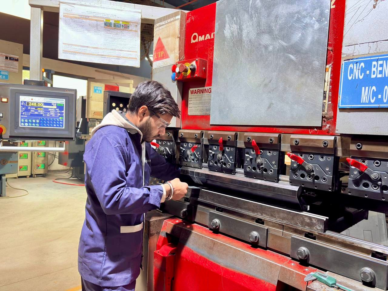
Our press shop includes mechanical and hydraulic presses suited to different part sizes, tonnage requirements, and cycle speed needs.
Shearing machines perform straight-line cuts to reduce full-size sheets into blanks for stamping or direct use. Shearing is faster and more material-efficient than laser for straight cuts on rectangular blanks.
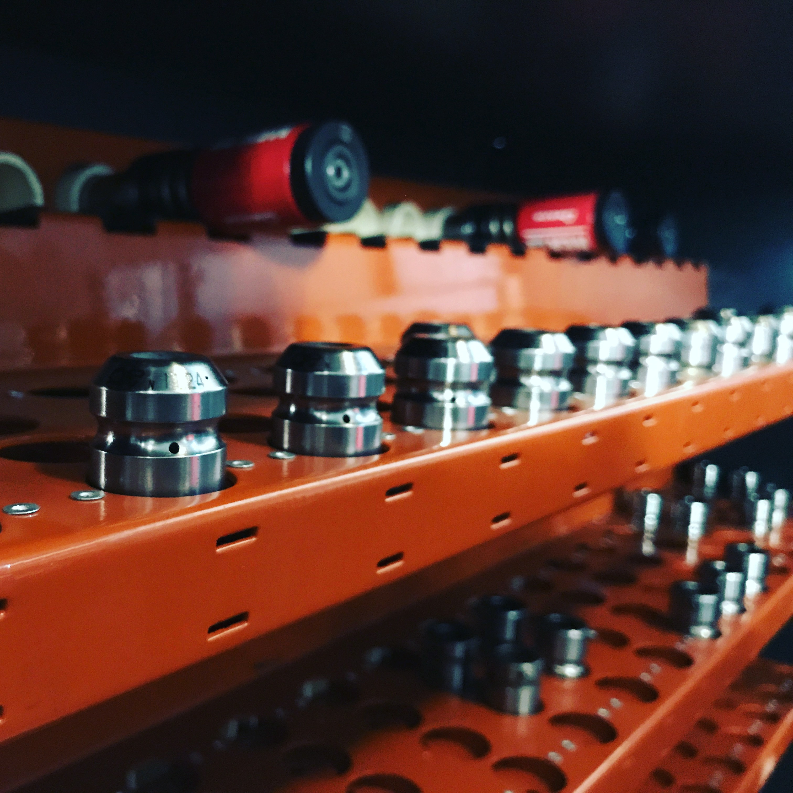
Each stamped part requires a dedicated die set (punch and die) that defines the part geometry. We build, maintain, and store tooling in-house for fast turnaround and ongoing production support.
Material is fed into the press either as pre-sheared blanks or as strip/coil, depending on the die type and production volume.
Blanking: Cutting the outer contour of a flat part from sheet metal. Produces the finished part shape in a single press stroke. Used for flat brackets, mounting plates, cover plates, and blanked panels.
Piercing: Punching holes, slots, and internal features into a part. Round holes, oblong slots, square cutouts, and ventilation patterns all produced by piercing punches in the die set.
Forming: Bending, drawing, or shaping the part within the die. Used for brackets with bent flanges, cable clamps, spring clips, and components requiring a 3D shape directly from the press.
Compound operations: Blanking and piercing combined in a single stroke — the part is blanked to shape and holes are pierced simultaneously. Produces a finished flat part in one press cycle.
Progressive operations: Multiple stations within a single die set, each performing a different operation (pierce, notch, form, blank) as the strip advances through the tool. The most efficient method for complex parts with multiple features at very high volumes.
Brackets and gussets: L-brackets, Z-brackets, corner gussets, mounting brackets — the most common stamped parts in any enclosure, used by the dozen in every rack and cabinet for structural reinforcement and component mounting.
Mounting plates and cover plates: Flat blanked parts with pierced mounting holes — used as blank panels, cover plates, and equipment mounting surfaces.
Cable clamps and clips: Formed parts that hold cables, harnesses, and conduit in place inside enclosures. Produced in high volumes across production programs.
Earth bars and busbar supports: Copper or mild steel bars blanked and pierced for earthing and power distribution hardware.
Hinge plates and lock strikers: Precision-blanked and formed parts for door hinge assemblies and locking mechanism components.
Ventilation louvres and grilles: Pierced and formed louvre patterns for airflow panels — produced in volume by progressive dies.
Reinforcement ribs and stiffeners: Formed channel sections that add structural rigidity to enclosure panels and doors.
Mild steel (CRC IS 513-D): 0.5–4.0 mm. The most common material for enclosure brackets and structural components. Excellent stampability and formability.
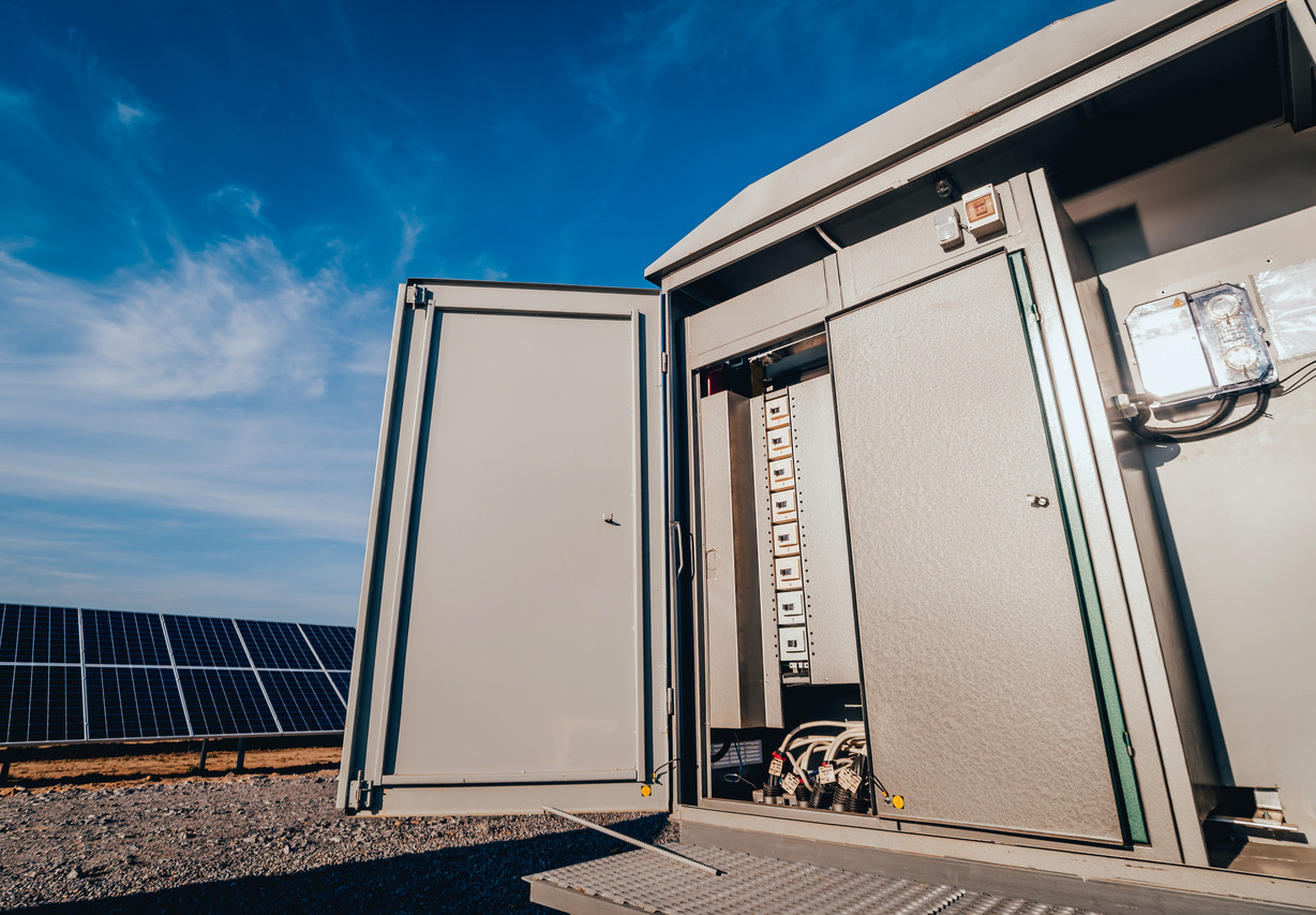
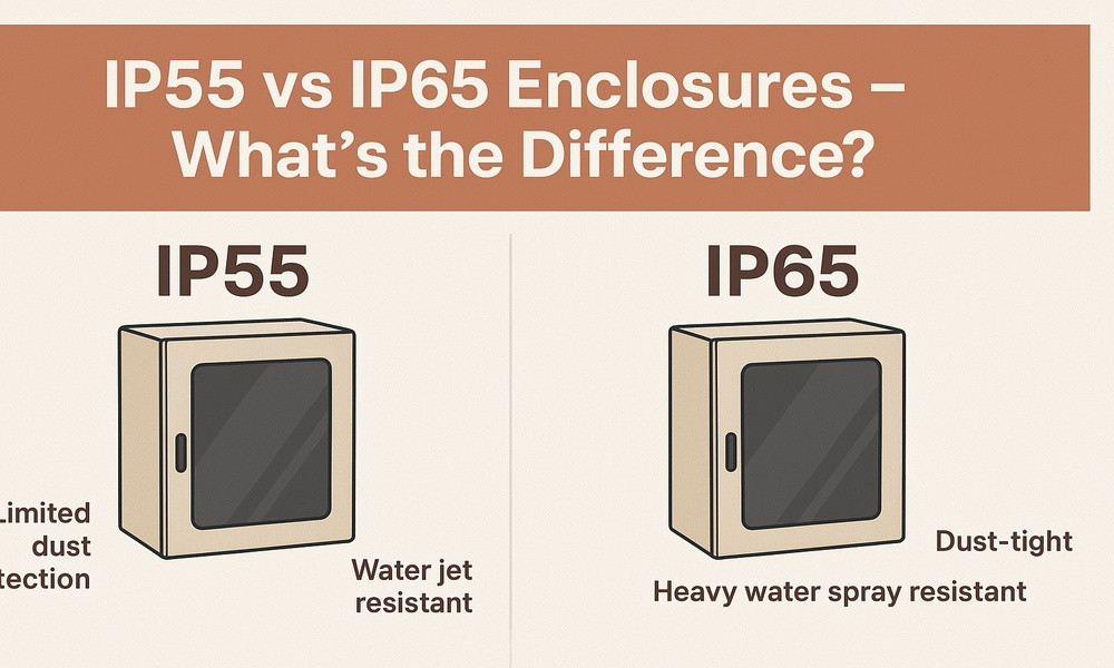
Galvanised steel (GI IS 277): 0.5–3.0 mm. Pre-coated zinc layer provides corrosion resistance without post-coating. Common for outdoor cabinet components.
Stainless steel (SS 304/316): 0.5–3.0 mm. Requires higher tonnage (approximately 50% more than CRC) and harder tool steel. Used for corrosion-critical and food-grade applications.
Aluminium (5052/6061): 0.5–4.0 mm. Soft and easy to stamp but requires attention to burr control and galling prevention. Used for lightweight components and heat sinks.
Copper and brass: Up to 3.0 mm. Stamped for earth bars, busbar components, and electrical contact parts.
Blanking dimensions: ±0.10–0.15 mm achievable on precision blanking dies for standard sheet thicknesses. Tolerance tightens with thinner material and higher-quality tooling.
Hole positions: ±0.10 mm on compound and progressive dies where holes are pierced relative to the blanked edge in the same die set (no repositioning error).
Formed dimensions: ±0.20–0.30 mm typical on formed features (bends, draws), with springback compensation built into the die geometry.
Shearing tolerances: ±0.25–0.50 mm on sheared blank dimensions, depending on material and thickness. Adequate for most downstream stamping and fabrication operations.
Burr height: Controlled by die clearance and tool sharpness. Maintained below 10% of material thickness for enclosure components (typically <0.1 mm on 1.0 mm CRC).
Part review & tooling design
DFM review • die concept • strip layout • tooling quote
Your part drawing is reviewed for stampability. Our tool designers determine the optimal die type (simple, compound, or progressive), define the strip layout for maximum material utilisation, and prepare a tooling quote alongside the per-piece production price.
Tool building & tryout
Die set fabricated • press tryout • first-off samples
The die set is built in-house (or sourced from our tooling partners for complex progressive dies), hardened, and assembled. Tryout is performed on the production press to produce first-off samples for dimensional verification.
Material preparation & shearing
Sheet stock sheared to strip width • optimised nesting
Full-size sheets are sheared into strips or blanks at the dimensions required by the die set. Strip widths are optimised during tooling design to maximise the number of blanks per sheet.
Press production run
Die set mounted • batch stamped • in-process checks
The die set is mounted in the press, stroke and shut height are set, and batch production begins. The operator feeds material and monitors output for visual quality and dimensional consistency.
Deburring, inspection, and release
Burr removal • dimensional check • batch release
After stamping, parts are deburred (if required), given a final dimensional inspection, and released to the next process stage — either forming, welding, powder coating, or direct to assembly.
Volume is high: Batch sizes of 1,000+ pieces, or recurring annual volumes where the tooling investment is recovered quickly across total production.
Part geometry is fixed: The design is finalised and will not change frequently. Tooling modifications are possible but cost time and money, so stamping favours stable designs.
Per-piece cost is the priority: At volume, stamped parts cost a fraction of laser-cut parts because cycle times are measured in seconds per piece (not minutes) and there is no CNC programming cost per batch.
Material efficiency matters: Shear + stamp workflow with optimised strip layout achieves higher material yield than laser nesting for simple geometries, because shearing has zero kerf and stamping waste is limited to carrier strip and slug.
Consistency is critical: Every part from the die is identical — no operator variation, no programming variation, no thermal distortion. Ideal for parts that must interchange across thousands of assemblies.
Volume is low: Prototypes, first-article batches, or one-off production where tooling investment cannot be justified.
Design changes frequently: Parts still in development, or products with frequent engineering changes. Laser cutting requires only a DXF file change — no physical tooling to modify.
Geometry is complex: Intricate contours, tight radii, internal cutouts, and shapes that would require expensive multi-station progressive dies to stamp.
Mixed production: Multiple different parts nested on the same sheet in a single laser run — possible with laser, not practical with stamping where each part needs its own die.
Lead time is urgent: Laser can cut parts within hours of receiving a drawing. Stamping requires tooling (typically 2–4 weeks for a new die set).
First-off approval: First pieces from every production run are measured against the approved sample and part drawing before batch production proceeds. Critical dimensions, hole positions, form angles, and burr height are verified.
In-process sampling: Parts sampled at regular intervals during the run (typically every 50–100 pieces) to detect tool wear, punch dullness, or dimensional drift before it produces non-conforming parts.
Final batch inspection: Dimensional check on a sample basis per AQL (Acceptable Quality Level) as agreed with the customer, or 100% inspection for safety-critical or tight-tolerance components.
Sharpening schedule: Blanking and piercing punches are sharpened at defined intervals (based on material type and stroke count) to maintain sharp cutting edges and control burr height.
Die clearance monitoring: Clearance between punch and die checked during maintenance to ensure it remains within specification (typically 5–10% of material thickness per side for clean blanking).
Tool life tracking: Stroke count logged per die set to trigger preventive maintenance at defined intervals and predict tool replacement timing.
Spare components: Wear items (punches, die inserts, springs, pilots) stocked or quick-sourced to minimise production downtime when replacement is needed.
Send your part drawing, material, and annual volume — we quote tooling + piece price within 24–48 hours.


-20082508144130.jpg)
-20082508385589.jpg)


-29112509574730.jpg)
-18122502213226.png)