-05112411185699.jpeg)

Eterna Global Solutions
C-52 Block-C, Sector 80
Noida Uttar Pradesh,
201306, India
Eterna Global Solutions
C-52 Block-C, Sector 80
Noida Uttar Pradesh,
201306, India
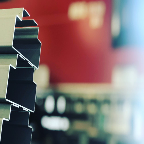
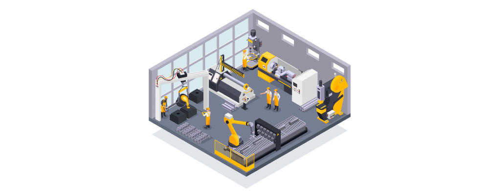
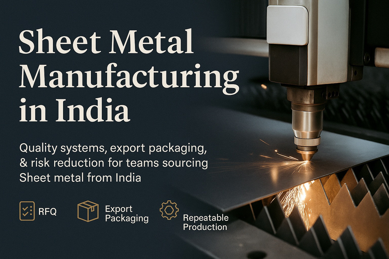
Eterna Global Solutions LLP operates multiple CNC press brakes — Japanese and Italian machines — at its Noida manufacturing facility, providing precision folding and forming for sheet metal enclosures, server racks, telecom cabinets, battery housings, brackets, panels, and OEM assemblies. Our press brakes deliver up to 130 tonnes of bending force over a 3,100 mm bending length, forming parts as narrow as 10 mm and as wide as 3,000 mm with angular accuracy of ±0.3° and dimensional repeatability of ±0.1 mm on formed features.
What sets our bending capability apart is our investment in fixed-height (European-style) segmented tooling. Unlike conventional tooling that requires re-shimming and height adjustment for each tool change, fixed-height tooling allows our operators to swap punch-and-die combinations without recalibrating the machine — enabling complex multi-bend parts in a single setup. For buyers, this translates to shorter setup times, fewer handling steps, lower per-part cost, and tighter bend-to-bend consistency across production batches. On typical enclosure components with 6–12 bends, fixed-height tooling reduces setup time by approximately 40–60% compared to conventional press brake setups.
Every bend at Eterna is programmed from our design team’s SolidWorks CAD data, with bend sequence, back-gauge position, tonnage, and springback compensation calculated before the first part is formed. Blanks arriving from our CNC laser cutting and punching cell are formed against validated programs, with first-piece dimensional inspection on every job. We operate our press brakes on a 24-hour schedule to support tight delivery timelines, handling everything from single prototype bends to recurring production programs of 500+ units/month.
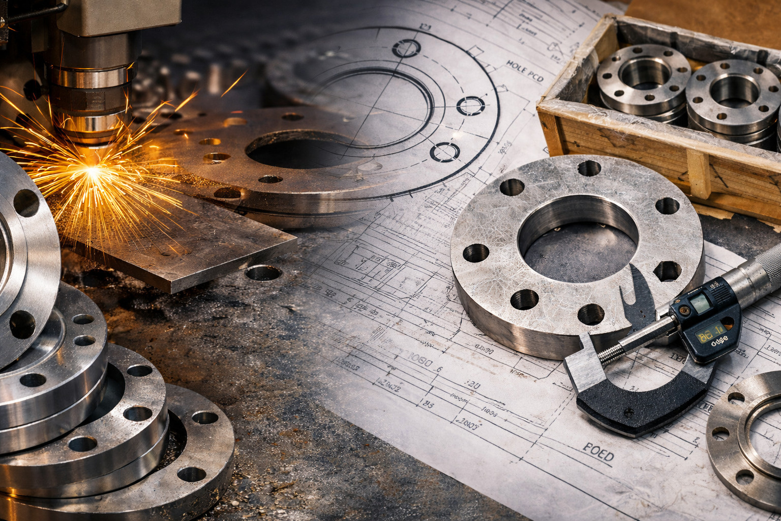
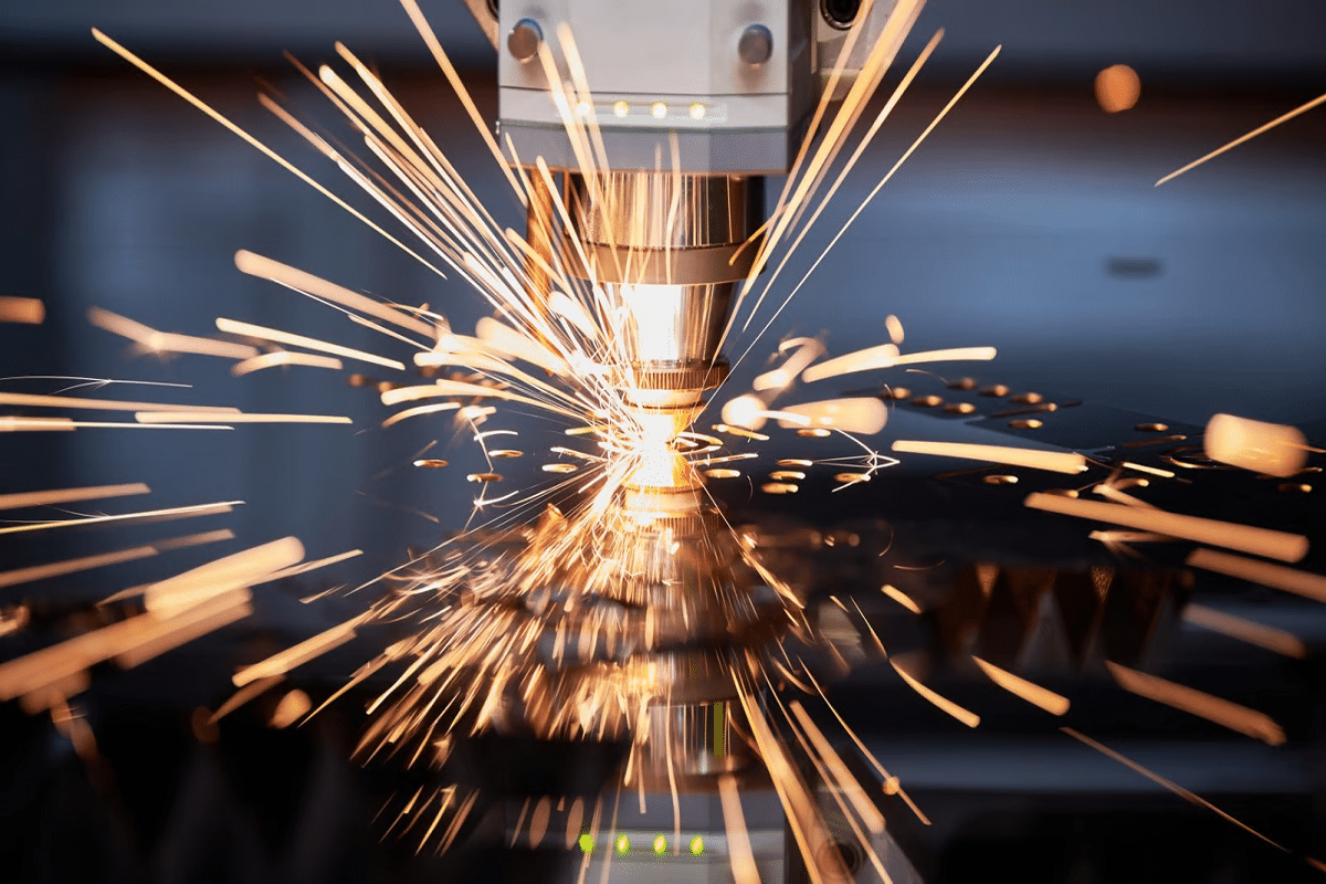
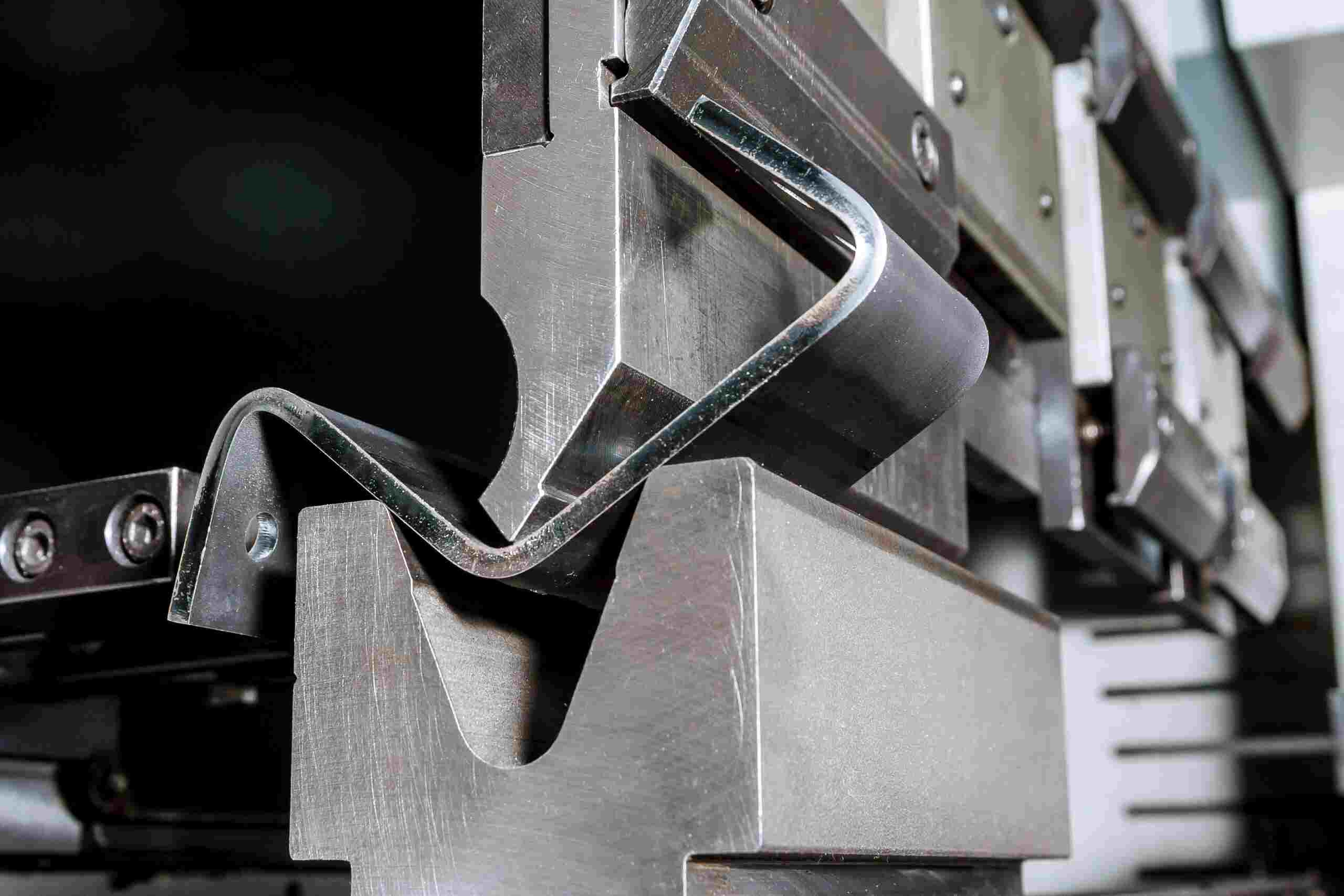
CNC folding (also called press brake bending) is the process of forming flat sheet metal blanks into 3D shapes by clamping the workpiece between a matched punch and die, then applying controlled force to create precise bends. It is the second major operation in sheet metal fabrication, following blanking (laser cutting/punching) and preceding welding, hardware insertion, and surface finishing. The accuracy of every bend directly determines whether parts fit together during assembly — making press brake precision critical to final product quality.
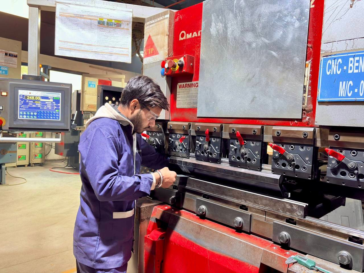
We operate multiple CNC press brakes with CNC-controlled back gauges (X, Y, R axes) that automatically position the blank for each bend in the sequence. Bend programs are generated from our SolidWorks CAD models with pre-calculated bend allowances, K-factors, and springback compensation values matched to each material type and thickness. Fixed-height segmented tooling allows complex multi-bend profiles in a single machine setup, and our operators verify first-piece dimensions against the drawing before batch production begins.
Our press brakes are Japanese and Italian-origin CNC hydraulic machines with servo-controlled rams and multi-axis CNC back gauges. The CNC controller stores bend programs so that recurring production jobs are recalled instantly with no re-programming.
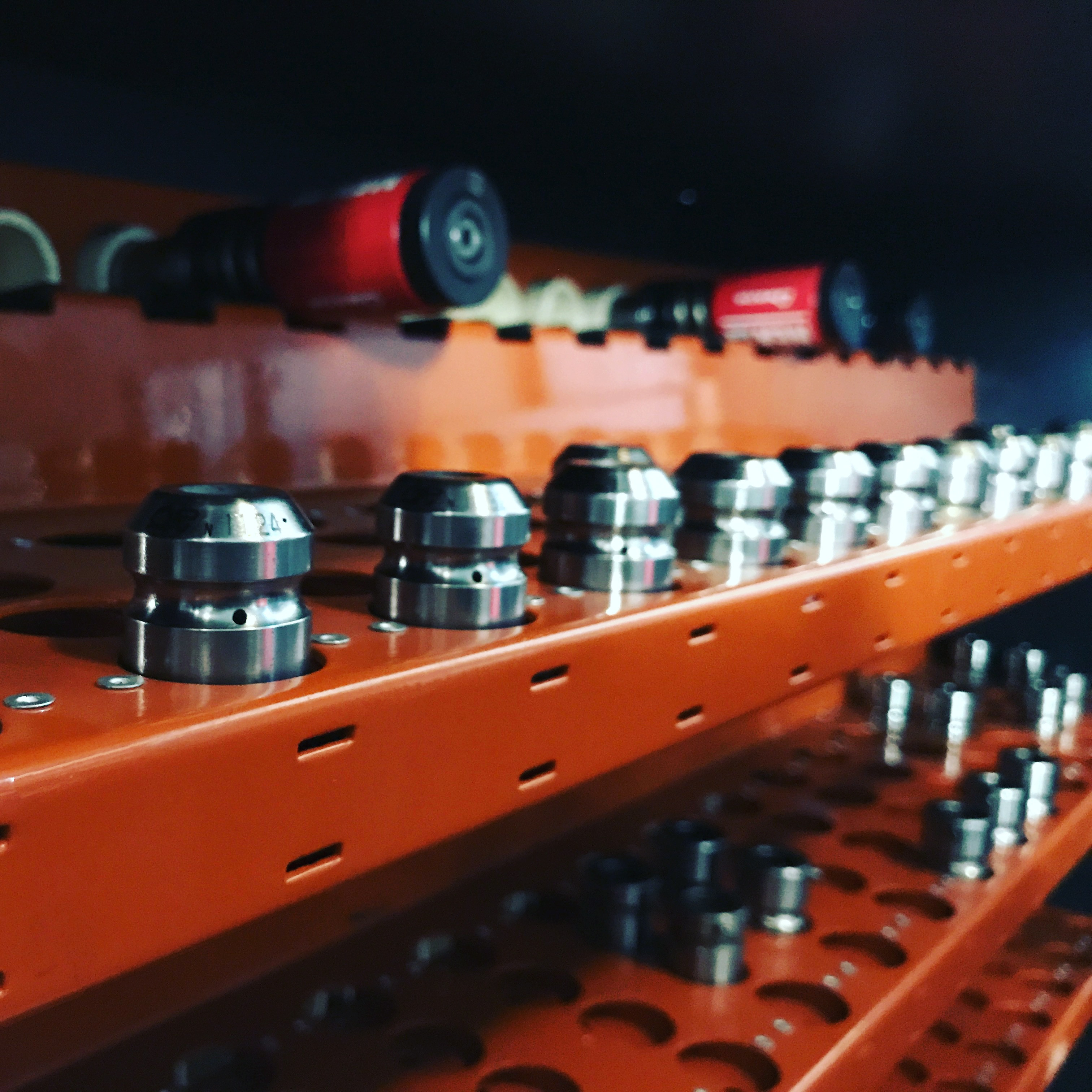
Fixed-height (also called “same-height” or “European-style”) tooling is our key advantage for complex enclosure parts. All punch and die segments have identical shut heights, so any combination of tool profiles can be loaded side-by-side without shimming or height adjustment — and the machine does not need recalibration when tools are swapped.
Every press brake job is programmed offline from CAD data before the operator loads the first blank. The program defines the complete bend sequence, back-gauge positions, tonnage per bend, and springback compensation — removing guesswork from the shop floor.
Bend angle accuracy is verified throughout the forming process using digital angle measurement tools. This ensures that the angular accuracy stated in our specifications (±0.3°) is maintained part-to-part and batch-to-batch.
Air bending (V-bend): The most common method. The punch presses the sheet into a V-die without bottoming — bend angle is controlled by punch depth. Produces bends from 30° to 175° with standard V-dies. Used for approximately 80% of all enclosure bends.
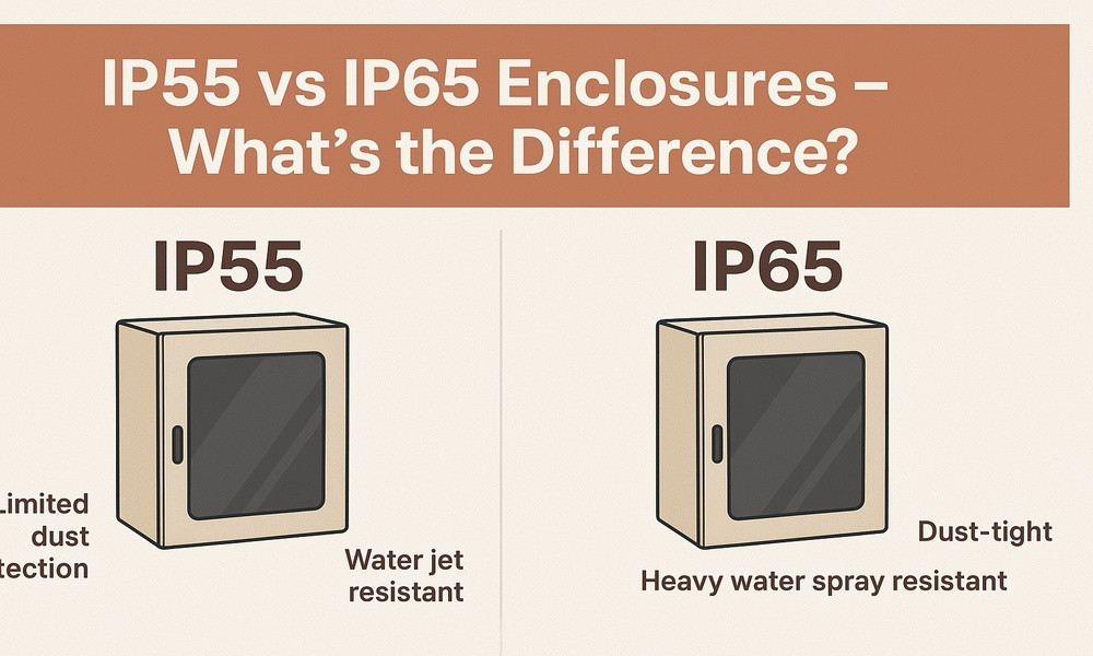
Bottom bending (coining): The punch presses the sheet fully into the die, compressing the material at the bend line. Produces tighter angular tolerance (±0.15°) than air bending but requires 3–5× more tonnage. Used for critical bends where angular precision is paramount, such as door frame alignment surfaces and gasket sealing flanges on IP-rated enclosures.
Hemming: A two-stage operation that folds a sheet edge 180° back onto itself, creating a smooth, rounded, safe edge with doubled material thickness. Standard on enclosure door edges, panel edges, and anywhere end-users handle the product.
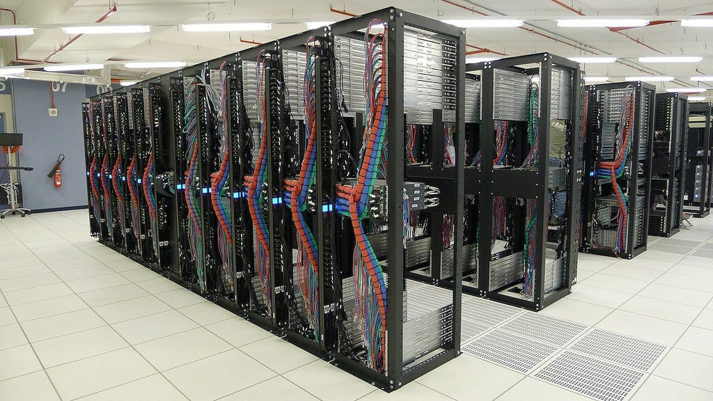
Z-bends (offset bends): Two bends in opposite directions creating a stepped profile. Used for overlapping flanges, panel offsets, and cable routing channels in server racks.
Channel forming (U-bend): Multiple bends creating a C or U cross-section in a single part, commonly used for structural members, cable trays, and chassis frames.
Radius bending: Progressive or single-stroke bends creating a curve rather than a sharp angle. Used for curved enclosure corners, radius panels, and aesthetic applications. Achieved using radius punch/die tooling matched to the required radius (typically R5–R50 mm).
Gooseneck bending: Using gooseneck-profile punches to reach into previously formed flanges without collision. Essential for box shapes, deep enclosures, and C-channel profiles where standard punches would collide with the already-bent flange.
Our minimum inside bend radius is 1× material thickness for mild steel and galvanized steel, and 1.5× material thickness for stainless steel 304/316 and aluminium, to prevent cracking at the bend line. Minimum flange length (from bend line to sheet edge) is 4× material thickness or 6 mm, whichever is greater. These parameters are validated during our DFM review stage before any production begins.
V-die opening directly affects bend radius, required tonnage, and minimum flange length. Our standard rule: V-die opening = 6–8× material thickness. For 1.0 mm CRC, we use a 6 mm V-die. For 2.0 mm CRC, a 12–16 mm V-die. For 3.0 mm SS 304, an 18–24 mm V-die. Wider V-die openings produce larger radii and require less tonnage but need longer minimum flanges. This trade-off is managed during bend programming to optimise for the specific part geometry and tolerance requirement.
Job card & bend program recall
Program loaded • tooling selected
The operator receives a job card specifying the part number, drawing revision, material, quantity, and the pre-programmed bend program ID. The CNC controller recalls the stored program, which defines every bend in sequence: back-gauge position, ram depth, tonnage, and tool station.
Tool setup & alignment
Fixed-height tooling • quick-clamp • die alignment
The operator loads the required punch and die segments as specified by the bend program. With fixed-height tooling, multiple tool profiles are loaded side-by-side without height adjustment.
First-piece forming & inspection
Trial bend • dimensional check • angle verification
The first blank from the batch is formed through the complete bend sequence. After forming, the operator performs a full dimensional inspection of the first piece against the production drawing.
Batch production forming
CNC repeatability • operator monitoring
Once the first piece is approved, the operator proceeds with batch forming. CNC repeatability (±0.01 mm ram, ±0.02 mm back gauge) ensures each part replicates the approved first piece.
In-process sampling & batch inspection
Random checks • drift prevention • batch release
During batch production, parts undergo random sampling inspection at defined intervals (typically every 10th or 20th part, depending on batch size and criticality). This catches any dimensional drift before it propagates through the batch.
Cold Rolled Steel (CRC/CRCA): IS 513-D, 0.5–4.0 mm. The most commonly bent material at Eterna. Excellent formability, predictable springback (~1–2° at 90°), and consistent results. Standard for indoor enclosures, server rack panels, brackets, and internal structural parts.
Hot Rolled Steel (HRC): IS 2062 Gr. E250, 2.0–6.0 mm. Bent for heavy-duty base frames, mounting brackets, and structural gussets. Higher springback than CRC (~2–3°), requiring adjusted overbend angles in the program.
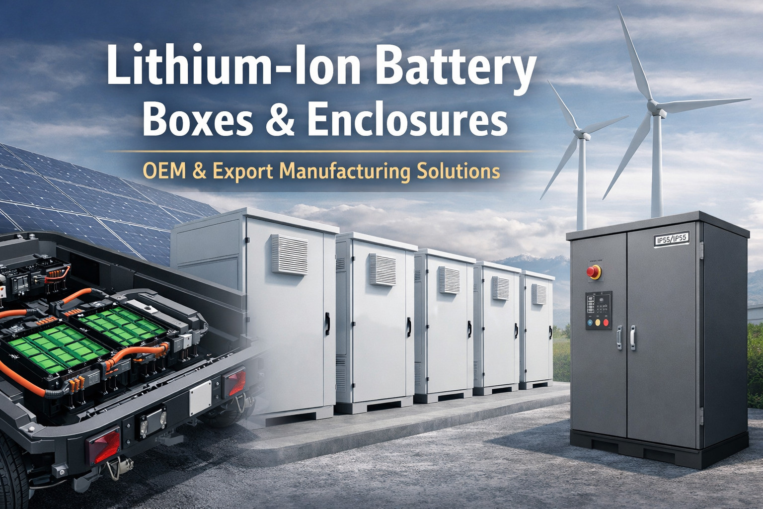
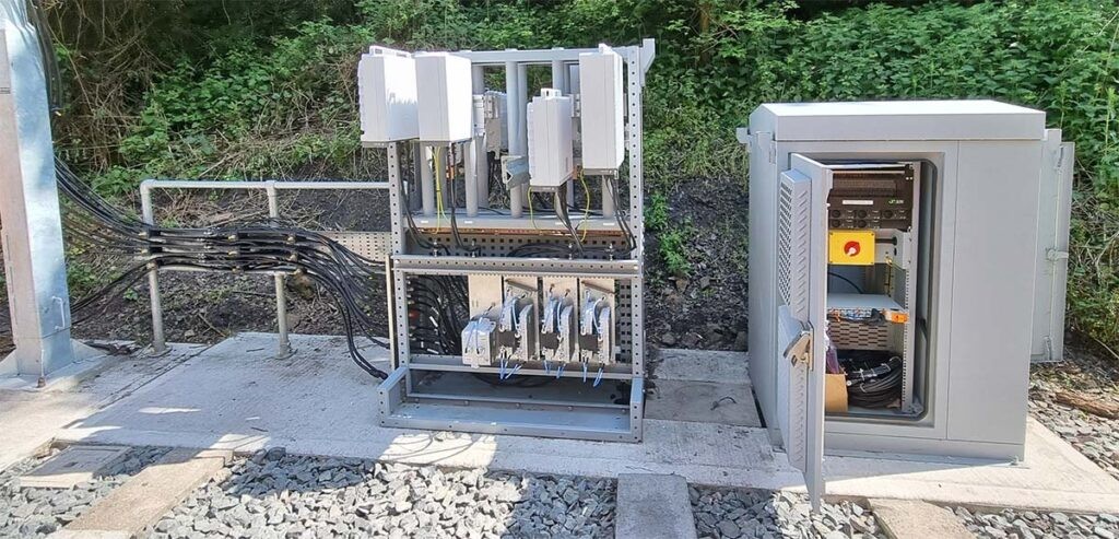
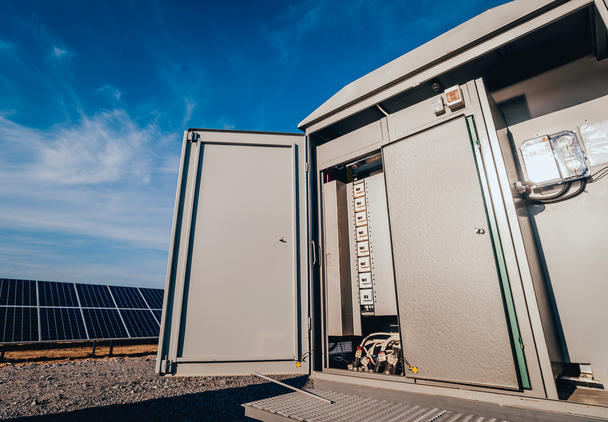
Galvanized Steel (GI/GP): IS 277, 0.6–3.0 mm. Standard for outdoor telecom cabinets and battery enclosures. Bends well with care to prevent zinc flaking at the bend line on tight radii. Minimum inside radius 1.5×t recommended to preserve zinc coating integrity.
Stainless Steel: SS 304 and SS 316, 0.5–4.0 mm. Significantly higher springback than mild steel (~3–5° at 90°) and requires approximately 50% more tonnage. Our bend programs include material-specific springback tables for SS grades to achieve target angles on the first piece.
Aluminium: 5052-H32 and 6061-T6, 0.8–4.0 mm. 5052-H32 bends well with standard radii. 6061-T6 is significantly less formable and requires larger bend radii (min. 2×t to 3×t) to prevent cracking. We advise on grade selection during DFM review based on the required bend geometry.
Copper and brass: Bendable on our press brakes in thicknesses up to 3.0 mm. Soft materials with low springback, but require non-marking tooling (polyurethane die inserts) to prevent surface damage on decorative or electrical-grade applications.
Approximate press brake tonnage per metre of bend length (for air bending with 8×t V-die opening):
1.0 mm CRC: ~7 tonnes/m
2.0 mm CRC: ~25 tonnes/m
3.0 mm CRC: ~55 tonnes/m
2.0 mm SS 304: ~38 tonnes/m
3.0 mm SS 304: ~82 tonnes/m
Our 130-tonne capacity comfortably handles these loads at full bending length (3,100 mm) for all standard enclosure thicknesses.
Every forming job follows a first-piece approval + in-process sampling discipline. The first piece is fully dimensionally inspected against the production drawing. Critical measurements include bend-to-bend distances, bend-to-hole positions, overall formed dimensions, and bend angles. Subsequent parts are randomly sampled (1-in-10 standard, 100% for critical applications). All measurements are recorded on the job card and retained for traceability.
Press brakes undergo monthly preventive maintenance covering hydraulic system checks, ram parallelism verification, back-gauge calibration, and crowning system verification. Tooling is inspected for wear (punch tip radius and die shoulder radius) on a weekly cycle — worn tools produce inconsistent bend angles and are replaced before they affect part quality. Annual third-party calibration of CNC axes ensures long-term positional accuracy.
Digital protractor (0.05° resolution), digital vernier calipers (±0.01 mm), height gauges, inside micrometers, depth gauges, steel rules, and go/no-go angle templates. All instruments calibrated annually per ISO 17025 traceable standards. For first-article inspections, full dimensional reports can be generated with measurement data per drawing callout.
A bend that is off by 0.5° or 0.3 mm may seem minor on a single part — but when 6 formed parts come together in a server rack or enclosure assembly, those errors compound. A door that doesn’t close flush, a rail that doesn’t align, or a gasket that doesn’t seal can all trace back to a bending error. This is why we invest in first-piece verification, CNC repeatability, and calibrated tooling — to ensure that every formed component fits correctly at assembly.
Send your drawings, 3D models, or flat patterns — we review bend feasibility, recommend tooling, and quote within 24–48 hours.


-20082508144130.jpg)
-20082508385589.jpg)


-29112509574730.jpg)
-18122502213226.png)